- Deutsch
-
EnglishDeutschItaliaFrançais日本語한국의русскийSvenskaNederlandespañolPortuguêspolskiSuomiGaeilgeSlovenskáSlovenijaČeštinaMelayuMagyarországHrvatskaDanskromânescIndonesiaΕλλάδαБългарски езикAfrikaansIsiXhosaisiZululietuviųMaoriKongeriketМонголулсO'zbekTiếng ViệtहिंदीاردوKurdîCatalàBosnaEuskeraالعربيةفارسیCorsaChicheŵaעִבְרִיתLatviešuHausaБеларусьአማርኛRepublika e ShqipërisëEesti Vabariikíslenskaမြန်မာМакедонскиLëtzebuergeschსაქართველოCambodiaPilipinoAzərbaycanພາສາລາວবাংলা ভাষারپښتوmalaɡasʲКыргыз тилиAyitiҚазақшаSamoaසිංහලภาษาไทยУкраїнаKiswahiliCрпскиGalegoनेपालीSesothoТоҷикӣTürk diliગુજરાતીಕನ್ನಡkannaḍaमराठी
Was ist ein Relais -Gerät?
- 2024/10/17
- 86
Katalog
Was genau ist ein Relais?
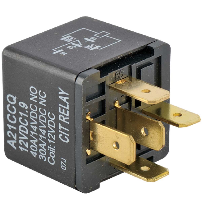
Ein Relais ist ein automatisches elektrisches Gerät, das in elektrischen Systemen verwendet wird, um die Signale zu steuern, zu schützen und zu ändern.Es hilft, die Wechselstrom- und DC-Schaltungen mit geringer Kapazität aus der Ferne zu verbinden und zu trennen.Dies ist erforderlich, um elektrische Systeme effektiv zu verwalten und zu schützen und gleichzeitig die Sicherheit zu gewährleisten.
Relais reagieren normalerweise auf elektrische Signale wie Strom oder Spannung, können aber auch auf Dinge wie Temperatur, Druck oder Geschwindigkeit reagieren.Wenn sie einen bestimmten Eingang erkennen, ändern sie die Ausgabe.Wenn ein Relais das richtige Signal erhält, kann es etwas ein- oder ausschalten.
In Autos ermöglichen Relais kleine elektrische Ströme, größere zu steuern.Dies schützt Schalter vor Schäden.Einige häufige Verwendungen von Relais in Fahrzeugen umfassen: Stromversorgungsrelais, Starterrelais, Hornrelais, Nebel -Lampen -Relais, Wischerrelais.Diese Beispiele zeigen, wie Relais die Kontrolle und Effizienz in verschiedenen Branchen verbessern.
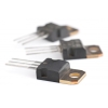
Elektromagnetische Relais bestehen aus grundlegenden Teilen wie Eisenkern, Spule, Anker, Rücklauffeder und Kontakten.Diese Komponenten arbeiten zusammen, um ihre Aufgaben auszuführen.Relais haben in der Regel eine Mischung aus normalerweise offenen und normalerweise geschlossenen Kontakten, mit denen Schaltkreise genau verwaltet werden.Ihr einfaches Design kann komplexe Ergebnisse erzielen.
Relais können auf unterschiedliche Weise klassifiziert werden, z. B. wie sie arbeiten oder wofür sie verwendet werden.Einige kombinieren normalerweise offene und normalerweise geschlossene Kontakte, um mehr Flexibilität zu erhalten.Es gibt auch bestimmte Arten von Relais für unterschiedliche Bedürfnisse, wie z.
Beispielsweise sind Zeitverzögerungsrelais perfekt für Situationen, die präzise Timing erfordern, z. B. die Steuerung von Montagelinienmaschinen.Die Vielfalt der Relaistypen unterstreicht ihre Bedeutung und Vielseitigkeit in modernen elektrischen Systemen.
Relaisleistung Metriken
Bewertungsspannung
Die bewertete Arbeitsspannung ist ein Muss für die Funktionsweise der Relaisspule.Es kann entweder Wechselstrom (Wechselstrom) oder DC (Gleichstrom) sein.Der Unterschied zwischen AC und DC zu kennen, ist wichtig, da es sich auswirkt, wie lange das Relais dauert und wie gut es unter verschiedenen elektrischen Lasten funktioniert.Die Wahl der falschen Spannung kann dazu führen, dass das Relais frühzeitig zusammenbricht.
DC -Widerstand
Der DC -Widerstand der Relaisspule wird häufig mit einem universellen Messgerät überprüft.Diese Messung hilft zu sehen, ob die Spule gut funktioniert.Wenn die Widerstandswerte ausgeschaltet sind, kann dies bedeuten, dass es Probleme wie Verschleiß oder Defekte gibt.Die regelmäßige Überprüfung dieser Messwerte ist von zentraler Bedeutung, um das Relais ordnungsgemäß funktionieren zu lassen.Um genaue Messwerte zu gewährleisten, ist es hilfreich, die Messwerkzeuge regelmäßig zu kalibrieren.
Einzugsstrom
Der Einzugsstrom ist die minimale Strommenge, die das Relais einschalten muss.Damit das Relais am besten funktioniert, sollte der gelieferte Strom über diesem Niveau liegen, aber nicht mehr als das 1,5 -fache der bewerteten Arbeitsspannung, um Schäden zu vermeiden.Dies ist ähnlich wie sicherzustellen, dass Haushaltsgeräte die richtige Spannungsmenge aus einem Steckdose erhalten, um elektrische Probleme zu vermeiden.Die Verwendung von Leistungsschalter oder Sicherungen kann dazu beitragen, den Stromfluss zu steuern.
Strom geben
Der Freigabestrom ist der maximale Stromniveau, auf dem sich das Relais ausschalten kann.Es sollte viel niedriger sein als der Einzugsstrom, um sicherzustellen, dass das Relais zuverlässig ausschaltet.Dies ist wie Sicherheitsmerkmale in Maschinen, die unter bestimmten Bedingungen vorhersehbar sind, um vorhersehbar zu sein.Das regelmäßige Testen dieser Parameter ist relevant, um potenzielle Probleme frühzeitig zu erfassen.
Kontaktschalterspannung und Strom
Die maximale Spannung und der Strom, den die Relaiskontakte verarbeiten können, setzen ihre Grenzen ein.Wenn diese Grenzwerte überschritten werden, kann sie die Kontakte beschädigen und das Relais zu Fehlfunktionen führen.Dies ähnelt den Sicherheitsmaßnahmen im elektrischen Design, die verhindern, dass Komponenten bei erwarteten Lasten ausfallen.In Umgebungen mit hohem Stress können die Verwendung von Sensoren und automatischen Überwachungssystemen dazu beitragen, diese Grenzen zu verfolgen, um Überlastung zu vermeiden.
Relais -Testtechniken
Um ein Relais ordnungsgemäß zu testen, müssen Sie einige wichtige Dinge überprüfen: Kontaktwiderstand, Spulenwiderstand, Einzugsspannung und Strom sowie Spannung und Strom frei.Sie können den Widerstand mit einem universellen Messgerät messen und die Spannung und den Strom mit einer einstellbaren Stromversorgung und einem Amperemeter überprüfen.Dieser Prozess stellt sicher, dass das Relais wie erwartet funktioniert.
Beginnen Sie mit der Messung der Kontaktwiderstand mit einem universellen Messgerät.Niedriger Kontaktwiderstand ist primär, da das Relais eine gute Verbindung herstellt.Wenn der Widerstand zu hoch ist, kann dies bedeuten, dass das Relais schmutzig oder abgenutzt ist, was zu Problemen führen kann.
Als nächstes messen Sie die Spulenwiderstand Verwenden des Universalmessers im Ohmmeter -Modus.Der Widerstand der Spule sollte den technischen Daten des Herstellers entsprechen.Wenn es zu hoch oder zu niedrig ist, kann es ein Problem mit der Spule des Relais geben, was zu einer schlechten Leistung führen kann.
Der Einzugsspannung und Strom Sagen Sie Ihnen, wann das Relais aktiviert wird.Verwenden Sie die einstellbare Stromversorgung, um die Spannung langsam zu erhöhen, und beobachten Sie den Strom auf dem Amperemeter.Beachten Sie beim Einschalten des Relais die Spannung und die Stromniveaus.Dies hilft Ihnen zu wissen, ob das Relais in seinem normalen Bereich arbeitet.
Danach messen Sie die Spannung und Strom freigeben.Senken Sie die Spannung langsam ab, bis sich das Relais ausschaltet, und schreiben Sie die Werte auf.Die konsequente Veröffentlichung stellt sicher, dass sich das Relais ausschaltet, wenn es soll, wodurch das System sicher bleibt.
Endlich, Überprüfen Dass die Spule arbeitet, indem sie Spannung anwendet und sieht, wie das Relais reagiert.Dies ist eine letzte Überprüfung, um sicherzustellen, dass das Relais reibungslos funktioniert.
Relais werden oft getestet, indem sie wiederholt ein- und ausgeschaltet werden, um ihre Ausdauer zu überprüfen.Ordnungsgemäße Tests und regelmäßige Überprüfungen sind erforderlich, um das Relais für lange Zeit zuverlässig zu halten.
Relais elektrische Symbole und Kontakttypen weitergeben
In elektrischen Diagrammen wird die Spule eines Relais als rechteckige Box dargestellt, sodass sie leicht zu identifizieren ist.Wenn das Relais zwei Spulen hat, werden zwei Rechtecke nebeneinander gezogen.Diese Methode sorgt für eindeutige und genaue Schaltungskonstruktionen.
Der Buchstaben "J" wird als Symbol verwendet, um das Relais in diesen Diagrammen darzustellen.Diese Kennzeichnung erleichtert das Verständnis und folgt den Standardpraktiken im technischen Bereich.
Relaiskontakte können je nach Schaltung neben der Spule oder getrennt angezeigt werden.Die Kontakte werden dadurch gruppiert, wie sie sich verhalten, wenn das Relais mit Energie versorgt (angetrieben) oder de-verstärkt (ausgeschaltet) ist.
• Normalerweise öffnen Sie Kontakte (nein) - Diese sind offen (aus), wenn das Relais ausgeschaltet und schließt (ein), wenn sie mit Energie versorgt werden.Sie sind nützlich in Systemen, in denen Geräte nur unter bestimmten Bedingungen betrieben werden sollten.
• Normalerweise geschlossene Kontakte (NC) - Diese sind geschlossen (eins), wenn das Relais ausgeschaltet ist und offen (aus) ist, wenn es mit Energie versorgt wird.Sie werden üblicherweise in Sicherheitsschaltungen eingesetzt, da sie im Falle eines Ausfalls wie einem Notstandsstopp die Stromversorgung fließen lassen.
• Kontakte ändern - Diese können zwischen normalen und normalerweise geschlossenen Zuständen wechseln, wodurch sie in automatisierten Systemen nützlich sind, in denen ein Relais mehrere Pfade steuert.Diese Vielseitigkeit verbessert sowohl die Effizienz als auch die Zuverlässigkeit bei der Verwaltung von Schaltungen.
Auswahl des Relais
Überprüfen Sie zunächst die Stromversorgungsspannung und den maximalen Strom sowohl für die Steuerschaltung als auch für die zu gesteuerte Schaltung.Dieser Schritt stellt sicher, dass alles reibungslos funktioniert.Der Steuerkreis muss genügend Strom bereitstellen, um das Relais zu aktivieren.Wenn der Strom zu niedrig ist, kann das Relais ausfallen und das Systemfehler riskiert.Es ist also großartig, sicherzustellen, dass genug Strom verfügbar ist.
Entscheiden Sie als Nächst Einpolige Einstürre (Spst) oder Doppelpole-Doppelwurf (DPDT).Der Typ hängt davon ab, was Ihr System erfordert.Die Auswahl des Rechten ist ein Muss für Leistung und Sicherheit.
Außerdem überprüfen Sie, ob der Steuerkreis die Relaisspule zuverlässig mit Strom versorgen kann.Wenn nicht, kann das System instabil werden.Die Gewährleistung eines konsistenten Stromversorgung ist wichtig für die Erstellung eines zuverlässigen Systems.
Überprüfen Sie die Spezifikationen des Relais wie Spulenwiderstand, Kontaktlastkapazität und Schaltgeschwindigkeit.Konzentrieren Sie sich nicht nur auf Spannung und Strom.Andere Funktionen müssen später auch Probleme vermeiden.
Wenn der Raum fest ist, wie in kleinen Elektronik, berücksichtigen Sie die Größe des Relais.Kompaktrelais können die Effizienz verbessern, ohne die Leistung zu beeinträchtigen, wählen jedoch sorgfältig aus, um Probleme mit der Haltbarkeit zu vermeiden.
Stellen Sie schließlich sicher, dass das Relais in die Leiterplatte oder an die Montage -Setup passt, ohne Änderungen zu benötigen.Ein gut angepasster Relais vereinfacht den Prozess und spart Zeit während der Montage, um sicherzustellen, dass alles nahtlos zusammenarbeitet.
Abschluss
Relais sind Geräte in elektrischen Systemen, die dazu beitragen, Signale zu kontrollieren, zu schützen und zu verwalten.Sie verbinden und trennen Sie die Schaltkreise und stellen sicher, dass alles reibungslos verläuft.Durch die Verwendung kleiner elektrischer Ströme, um größere zu steuern, schützen Relais empfindliche Teile vor Überlastungen und Fehlern, wodurch die Systeme für lange Zeit laufen.Es gibt verschiedene Arten von Relais, wie elektromagnetisch und thermisch, die für verschiedene Zwecke in Bereichen wie Herstellung und Telekommunikation verwendet werden können.Bei der Auswahl des richtigen Relais werden Dinge wie Spannung, Strom und Platz überprüft.Regelmäßige Tests und Wartung sind auch wichtig, um sicherzustellen, dass Relais gut funktionieren.Zu verstehen, wie Relais funktionieren, ist ein Muss für alle, die mit elektrischen Systemen arbeiten, da sie sicherstellen, dass alles sicher und effizient funktioniert.
Häufig gestellte Fragen [FAQ]
1. Was ist das Symbol des Relais?
Das Relais wird durch den Buchstaben K symbolisiert und das alte Symbol J. ersetzt. Wenn Sie verschiedene Arten von Relais angeben, wird ein Zwei-Buchstaben-Code zur Klarheit verwendet.Zum Beispiel bezeichnet KV ein Spannungsrelais, KA ist für ein Stromrelais, KT zeigt ein Zeitrelais an, KF ist für ein Frequenzrelais, KP bezieht sich auf ein Druckrelais, KC für ein Steuerrelais, KS steht für ein Signalrelais.und Ke ist für ein Erdungsrelais.
2. Welche Rolle spielt das Relais?
Relais haben wichtige Funktionen in elektrischen Systemen.Sie erweitern den Steuerbereich und verstärken die Steuersignale.Relais signalisieren auch Informationen und ermöglichen komplexe Interaktionen mit anderen Geräten.Durch das Erstellen von Steuerungsschaltungen ermöglichen Relais automatische Vorgänge, Fernbedienung und Überwachung.Sie fungieren als elektrische Steuergeräte, die Änderungen im Ausgangskreis basierend auf bestimmten Eingangsbedingungen auslösen.
4. Was bedeuten die NC, nein und com auf der Staffel?
In Relais steht NC für normalerweise geschlossen, was bedeutet, dass die Schaltung geschlossen ist, wenn keine Leistung vorliegt.NICHT Normalerweise öffnen sich, was darauf hinweist, dass die Schaltung ohne Strom geöffnet ist.Das COM oder das gemeinsame Terminal kann je nachdem, ob das Relais mit Energie versorgt wird, entweder mit NC oder NO herstellen.Diese Flexibilität macht Relais für verschiedene Kontrollanwendungen geeignet.
Verwandter Blog
-
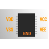
Netzteilspannung Abkürzung: VCC VDD VEE VSS GND
2024/06/6
Im modernen elektronischen Schaltungsdesign, Verständnis der Abkürzungen der Stromversorgungsspannung (wie VCC, VDD, VEE, VSS, GND).Diese Abkürzung... -
Ein Überblick über TTL- und CMOS -ICs und wie Sie zwischen ihnen wählen

2024/04/13
In diesem Artikel werfen wir einen detaillierten Blick auf zwei wichtige elektronische Technologien, komplementäre Metaloxid-Halbleiter (CMOS) und Tr... -
Verschiedene Arten von Sicherungen und Anwendungen

2024/04/18
Sicherungen sind wesentliche Komponenten in modernen elektrischen Systemen und fungieren als entscheidende Beschützer vor Überstrom.Sie arbeiten, in... -
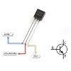
Verständnis des C1815 -Transistors: Pinouts, Schaltungssymbole, Anwendungsschaltungen
2023/12/20
Welche Art von Röhre ist der C1815?C1815 Triode PinoutC1815 ModellzeichnungC1815 -ParameterC1815 EigenschaftenAnwendung von C1815 Der C1815 -Transist... -
LR44 -Batterien: LR44 -Batterieäquivalente und LR44 -Batterieersatz
2024/01/24
In einem sich schnell entwickelnden technologischen Gebiet, in dem die Größe der elektronischen Geräte weiter schrumpfen und dennoch alltäglicher ... -
Grundkenntnisse über Sicherungen: Merkmale, Arbeitsprinzipien, Typen und wie man richtig auswählt
2024/04/10
Sicherungen schützen Schaltungen vor Schäden aufgrund von Überlastung oder Kurzstrecken.Dieses einfache, aber geniale Gerät basiert auf einem leic... -
Leitfaden zu Buck-, Boost- und Buck-Boost-Konverter
2023/12/21
Was ist ein Buck -Konverter?Wie funktioniert ein Buck Converter?Was ist ein Boost -Konverter?Wie funktioniert ein Boost -Konverter?Was ist ein Auftrie... -
Beschreiben Sie kurz die Spezifikationen, Verpackungen, das Arbeitsprinzip, die Vorteile und die Umweltauswirkungen von Lithium-Ionen-Batterien
2024/03/20
Seit der Einführung von wiederaufladbaren Blei-Säure-Batterien im Jahr 1859 wurden sie allmählich in den Gewebe des technologischen Fortschritts ei... -
Transistor (BJT und MOSFET) Arbeitsprinzipien
2023/12/20
Arbeitsprinzip des bipolaren Junction -Transistors (BJT)Auswahl der KomponentenwerteWie wählen Sie einen Transistor?Arbeitsprinzip von MOSFETWie scha... -
Grunde elektronische Grundkomponenten verstehen - Widerstände, Kondensatoren, Dioden, Transistoren, Induktoren und digitale Logik -Tore
2024/04/13
Elektronische Komponenten sind der Eckpfeiler des Bauens und der Optimierung elektronischer Schaltkreise.Von gewöhnlichen Haushaltsgeräten bis hin z... -
Beherrschen analoge und digitale Schaltungen: Ein Anfängerführer
2023/12/20
Definition und Eigenschaften von analogen Schaltungen und digitalen SchaltungenDer Unterschied zwischen analogen Schaltungen und digitalen Schaltungen... -
Eine vollständige Liste von Testmethoden für verschiedene Transistoren
2023/12/20
Der Transistor wurde von John Bardeen, William Shockley und Walter Brattain erfunden.Es handelt sich um ein Kollektor-, Emitter- und Basis-Drei-termin... -
Gesamtzahl der Transistoren in einer CPU
2024/06/14
In der modernen Computertechnologie ist die Beziehung zwischen der zentralen Verarbeitungseinheit (CPU) und den Transistoren zunehmend integraler gewo...
Heiße Teile
- GCM1885C2A181JA16D
- CGA4J3X8R1C105K125AD
- 04023A3R6BAT2A
- 12102U2R4DAT2A
- 12067A8R2CAT2A
- 12067C102JAT2A
- CGA6M3X7S2A335K200AE
- 1812AA121JAT1A
- 2220GC102KAT1A
- TACR226K006XTA
- ABS07-32.768KHZ-T
- FQP13N10
- ADS131A04IPBSR
- ADS7835EB/250
- S9S08DZ60F2MLHR
- 5CSEMA4U23C8N
- SN65LVDS9637DGNR
- BQ24140YFFR
- TLC59581RTQR
- ADP7102ACPZ-R7
- TLC7628CDWRG4
- MAX202ECPE+
- MAX491ECSD
- SN74LS33D
- RP20-2415DAW/N
- FS150R17KE3G
- UPC1093T-E1-AZ
- XR2404CJ
- ICS9148BF-17
- IRLML2402
- K9G8G08U0A-PCB
- R8J03020FP#RFJZ
- BH7641FV
- F731874GHH
- UPD75P316BGK-BC9
- PM5326-FGI
- ATSAMDA1G16B-ABT
- T491B225K020ZTPL11
- AT8356270-AQ4T
- PEF24622EV2.1-G
- S71WS256PDOHH3SR0
- STC15F2K60S2-28I-LQFP44
- MB95F634K
- SVF667580CMK4
- VII-CAM-1
- LTC1877IMS8
- K7R160982B-EC25
- S29GL064M11FFIS40